Connecting Devices
Cable each Device to the rear panel, create it in the ProPatch app, give it a Node for each signal path, then assign each Node's Port IDs. Chains are built from Nodes, so do this first. For what Devices, Nodes, and Port IDs are, see How ProPatch Works.
Cable your Devices
The rear labels describe signal flow relative to the ProPatch:
- IN FROM DEVICE receives a signal from a Device's output.
- OUT TO DEVICE sends a signal to a Device's input.
Device output → IN FROM DEVICE → relay matrix → OUT TO DEVICE → Device input
| Node type | Device output → | Device input ← |
|---|---|---|
| Source (preamp, D-A converter, tie line from the live room) | IN FROM DEVICE | — |
| Processor (compressor, EQ, effects) | IN FROM DEVICE | OUT TO DEVICE |
| Destination (A-D converter, monitor controller, recorder) | — | OUT TO DEVICE |
Tip: Use the same channel number for a Processor's send and return (for example, OUT TO DEVICE
C3and IN FROM DEVICEC3). The ProPatch app doesn't require it, but it makes the wiring easier to trace.
If you route phantom-powered microphones, don't send 48 V to line-level equipment, and read the phantom power precautions before you repatch a mic path. For connector details and front-panel Port IDs, see Hardware Reference.
Wire in stages
Don't connect the whole room and then start configuring. You cabled one Source and one Destination in the Quick Start; build out from there:
- Add one Processor, create its Device and Node, and test the round trip in a Chain.
- Add the remaining Devices in small, labeled groups, testing each group before the next.
Keep a wiring record that maps every cable to its Port ID. When you move a cable, update the Node's Port ID at the same time.
Create a Device
- Select DEVICES in the browser (G).
- Select + NEW DEVICE in the header (Shift+N).
- In CREATE DEVICE, optionally enter Manufacturer and Product; they fill in Device Display Name.
- Edit Device Display Name to a short, unique label, such as
1176 1orMTRX. - Select OK.
The new Device opens with one Mono Processor Node. Change its type if needed, then assign its Port IDs.
Keep a box's channels under its one Device: a four-channel mic pre is one Device with four Processor Nodes. A converter is one Device: its outputs are Source Nodes and its inputs are Destination Nodes. One Device per channel still routes audio but makes searching and troubleshooting harder.
The Device editor
Select a Device in the DEVICES browser to open it. This is the Demo Session's Eventide H90.
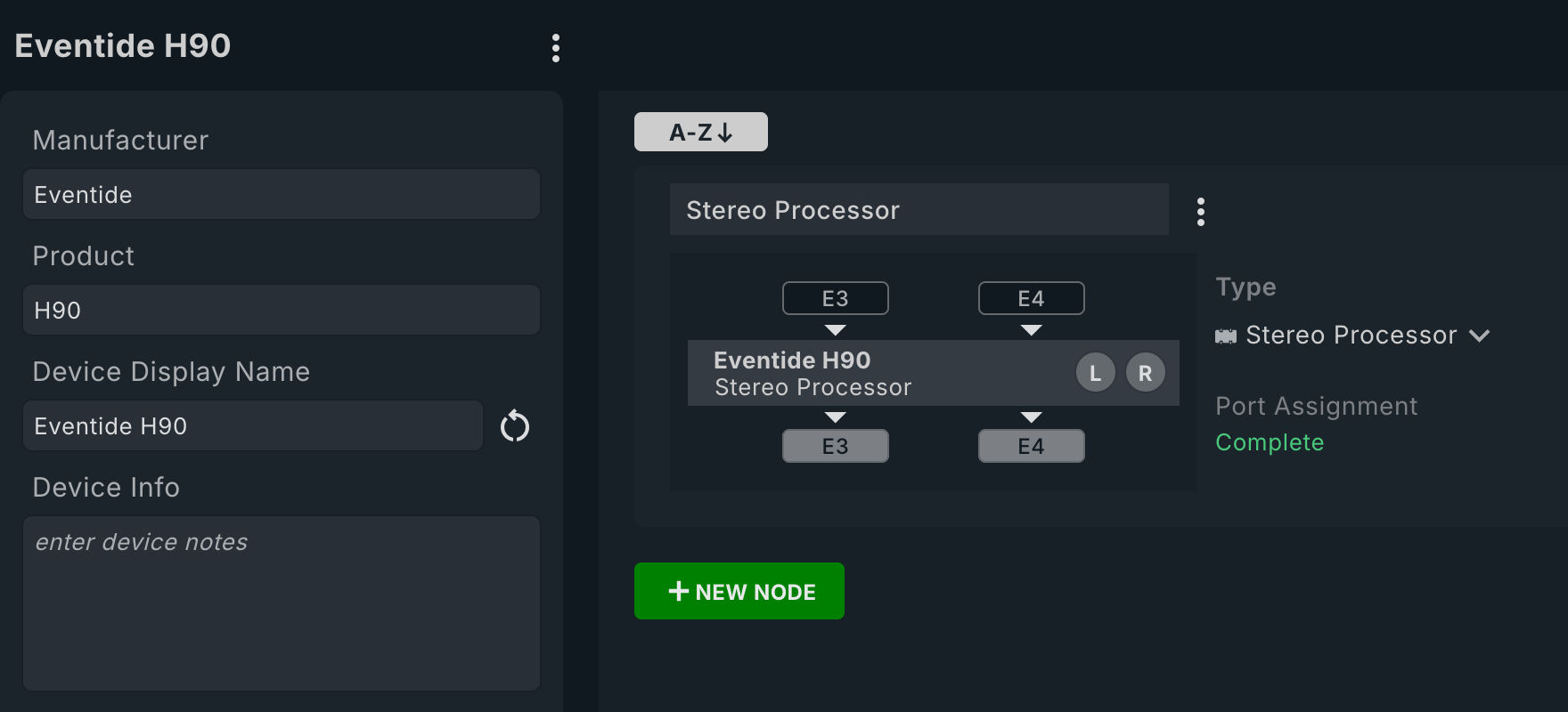
| # | Control | What it does |
|---|---|---|
| 1 | ⋮ Device menu | Duplicate or Delete the Device. |
| 2 | Manufacturer and Product | Optional details that identify the Device. |
| 3 | Device Display Name | The name you see while routing. |
| 4 | Restore name ↺ | Rebuilds the display name from Manufacturer and Product. |
| 5 | Device Info | Free-form notes about wiring or operation. |
| 6 | Node name | Double-click to rename. |
| 7 | ⋮ Node menu | Duplicate or Delete the Node. |
| 8 | Out (to) ports | Where ProPatch sends to the Device: here E3 and E4. |
| 9 | In (from) ports | Where the Device returns to ProPatch. |
| 10 | Type | See Node types. |
| 11 | Port Assignment | Complete or Incomplete. |
| 12 | + NEW NODE | Adds a Node to this Device. |
| 13 | Node sort | A-Z / Z-A sorts the Node cards and saves the order. You can also drag cards. |
Add a Node
- Open the Device and select + NEW NODE.
- In CREATE NODE, choose the Type.
- Enter a Name for its job, such as
Vocal ComporMic In 3. - Select OK.
Names must be unique within a Device and type, so a converter can have a Source 1 and a Destination 1.
Node types
Choose by how the signal uses the Node, not by what the Device is.
| Type | Use it for | Channels needed |
|---|---|---|
| Mono Source | Starts a Chain: converter output, tie line, front-panel input | 1 In (from) |
| Stereo Source | Stereo pair that starts a Chain | 2 In (from) |
| Mono Processor | Out to a box and back: compressor, EQ, mic pre | 1 Out (to), 1 In (from) |
| Stereo Processor | Stereo pair out and back | 2 Out (to), 2 In (from) |
| Mono to Stereo Processor | Mono out, stereo back: some reverbs | 1 Out (to), 2 In (from) |
| Mono Destination | Ends a Chain: converter, recorder, or monitor input | 1 Out (to) |
| Stereo Destination | Stereo pair that ends a Chain | 2 Out (to) |
Never model a converter channel as a Processor. Changing a Node's type removes Port IDs the new type doesn't use.
Assign Port IDs
Port labels read from the Device's side:
| Editor label | Direction | Rear-panel jack |
|---|---|---|
| Out (to) | ProPatch → Device input | OUT TO DEVICE |
| In (from) | Device output → ProPatch | IN FROM DEVICE |
- Select a port box on the Node card.
- Choose a Port (A, B, … or
FPfor the front panel), then the channel. Each channel shows the Device and Node already using it. - Repeat until Port Assignment reads Complete.
Unassign clears a channel. An incomplete Node is listed in NODES but can't be added to a Chain.
Two Nodes can share Port IDs, such as a stereo Node and two mono Nodes on one pair, but they can't be active at the same time. See Port ID Conflicts.
Show port overlays
Hold O to show Port IDs on every Node in the browser and on Chain cards. Press Shift+O to keep them on until you press it again.
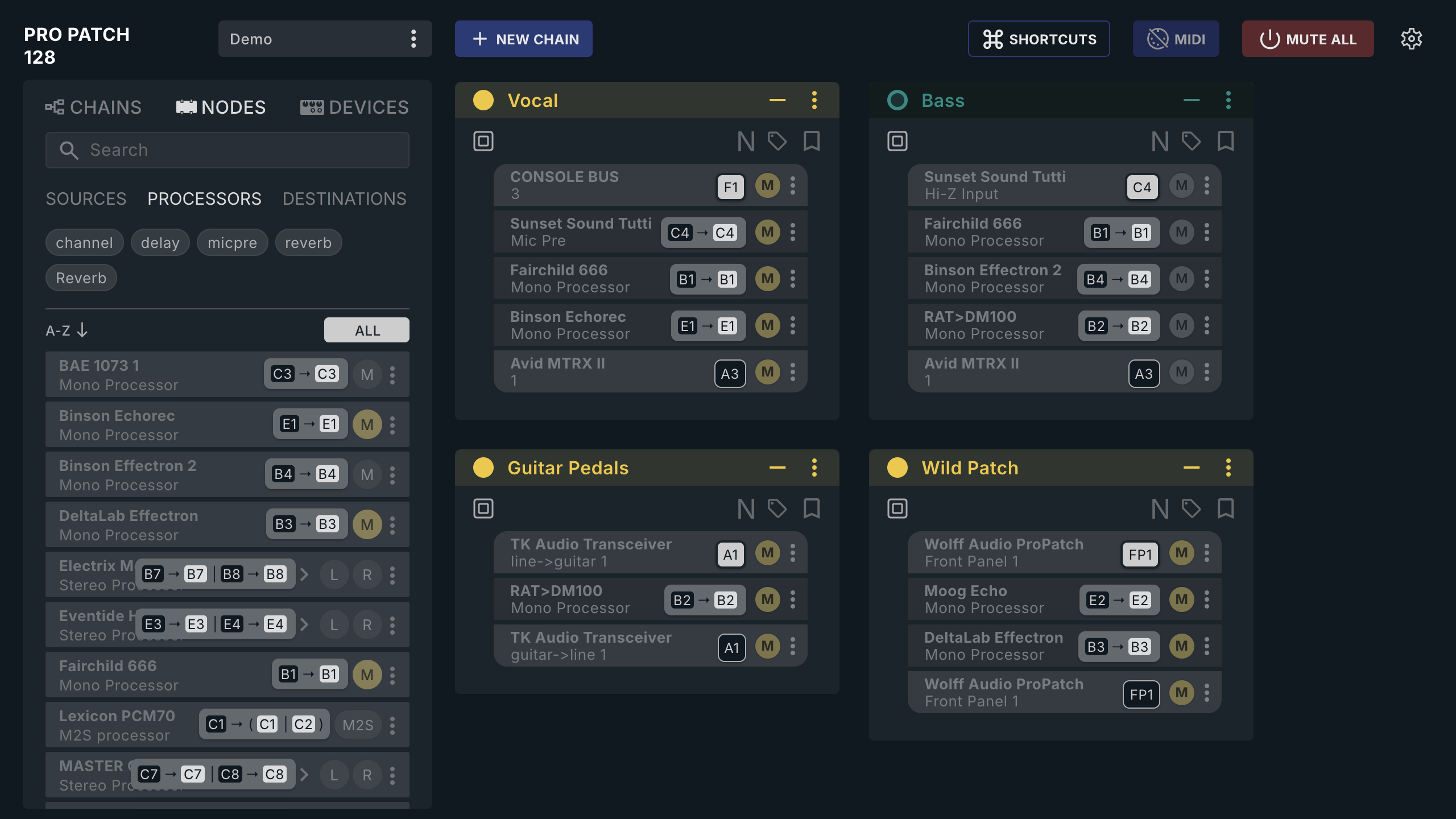
| Overlay | Meaning |
|---|---|
F1, FP1 |
Source or Destination (F1 | F2 if stereo) |
B1 → B1 |
Mono Processor: dark = ProPatch output to the Device, light = ProPatch input from it |
B7 → B7 | B8 → B8 |
Stereo Processor, left and right pairs |
C1 → ( C1 | C2 ) |
Mono to Stereo Processor: one send, two returns |
Rear IDs are a Port letter plus channel number (A1–A8, B1, …); front-panel IDs are FP1, FP2, …. Older files with P or TT prefixes are read as FP.
Move a connection
Change the Port IDs on the existing Node; every Chain that uses it follows. Deactivate the Chains using the old or new Port IDs first, then test for relay clicks and audio.
While a Chain uses a Node, you can't change its type or unassign its channels (Cannot modify type: … / Cannot unassign port: One or more chains reference this node).
Use one side of a stereo Node
In NODES, double-click a stereo Node's L or R chip, or open its chevron and double-click a sub-row, to add that side to the selected Chain.
Tag Nodes
Select + under Tags on a Node card (ADD TAG on a Node with none), then pick a tag, or type a new one and choose Create “name”. Tag by function (micpre, return); tags become filter chips in NODES.
Duplicate a Node or Device
For repeated channels, set up one Node, choose ⋮ › Duplicate, then assign new Port IDs to the copy. The copy keeps the original's type, Port IDs, and tags, so the two conflict until you reassign. Names get numbers: duplicating Mono Source gives Mono Source 1 and Mono Source 2.
Device ⋮ › Duplicate copies the whole Device, Nodes and Port IDs included, under the next free numbered name.
Delete a Node or Device
- Node: ⋮ › Delete, no confirmation.
- Device: ⋮ › Delete removes it and its Nodes, no confirmation. On macOS, Command+click it in the DEVICES browser asks DELETE DEVICE? first.
While a Chain uses it, the delete is refused (Cannot delete: One or more chains reference this node / …nodes/ports of this device). Command+Z undoes Device and Node edits, up to 100 steps.
Import and export Devices
System Configuration › DEVICES imports and exports Devices as CSV; import replaces all Devices and Chains. See Sessions, Files, and Backups.
Check your work
Before building Chains, confirm that each box has one Device, each Node has the right type, the Nodes you need read Complete, and shared Port IDs are intentional. Then continue to Chains.